Soldering Notes:
If you’re new to soldering, we highly recommend reading through a good soldering tutorial, such as the ones by Adafruit and SparkFun.
We recommend using only lead-free solder and a good quality, temperature-controlled soldering iron set to 750F/400C.
When soldering, clean the soldering tip often. We recommend using a brass wire sponge. After cleaning, melt a small amount of solder onto the tip of the iron.
Using the high 750F/400C temperature should mean that you don’t need to heat the pads for more than a few seconds at at time. This allows you to work more quickly and avoid overheating and damaging the pads or any components.
If you’re having a hard time getting the solder to melt, check your temperature.
If the solder is sticking to the iron but not the pads, you may not be heating the pads long enough, but it should only take a few seconds. You can use soldering flux, which may help.
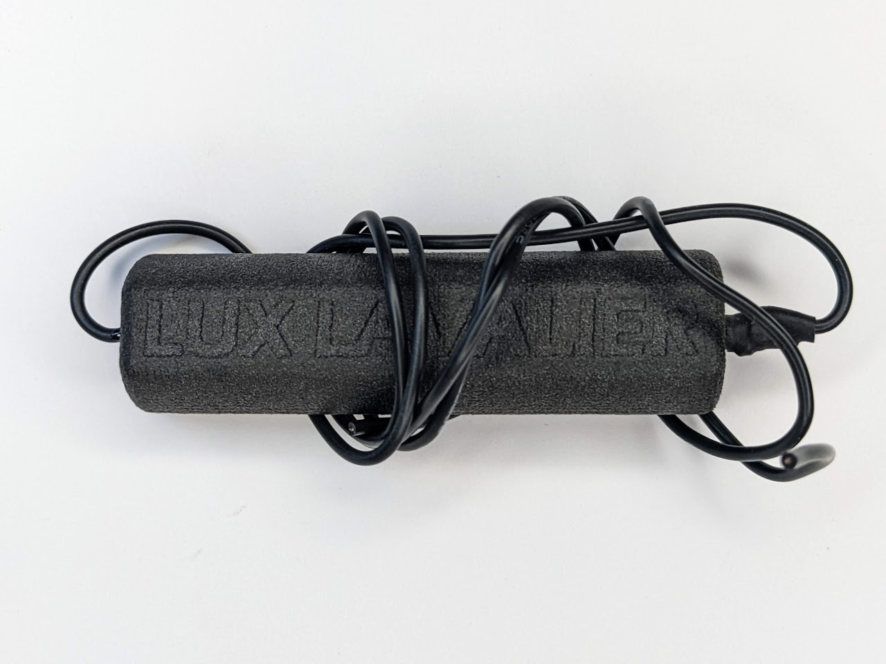
Trimming and soldering the magnetic wearable battery connector necklace:
-
Unwind, unwrap, and gently straighten the wires by holding the wire at the battery holder. Gently grip the wire with your other hand and run it down the length of the wire. Repeat until the wires are fairly straight. They do not need to be perfectly straight, and may still have a curve to them.
-
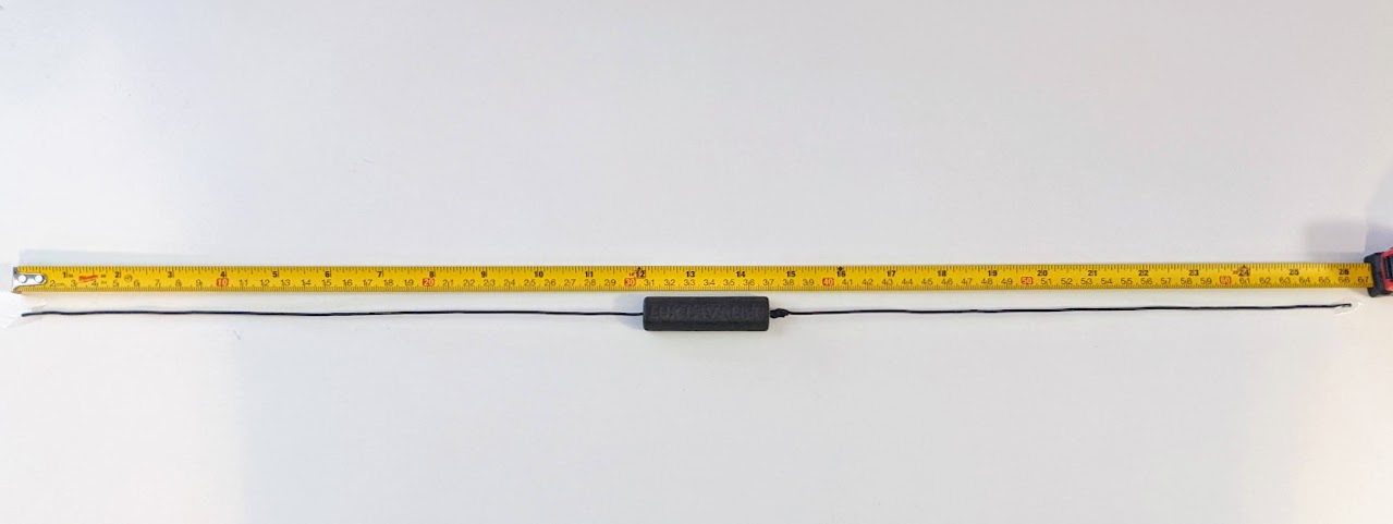
Your Lux Lavalier necklace wires will come approximately between 24” and 26”. The wires will need to be trimmed to the length you desire.
Determine your desired length by holding the pendant where you’d like it to hang. Then wrap the wires around to the back of your neck where the battery holder will rest on the nape (base) of your neck, with one wire in each hand. Ensure the pendant still rests where desired, pinch the wires on the back of your neck, then lay it out on a flat surface.
Measure the distance between your hands. That’s the total length we’ll trim the wires to, including the width of the battery holder.
Common necklace lengths are in two inch increments from 14” or 16” (for a “choker” necklace), 18” for a “princess”, 20” to 24” for a “matinee”, etc.
-
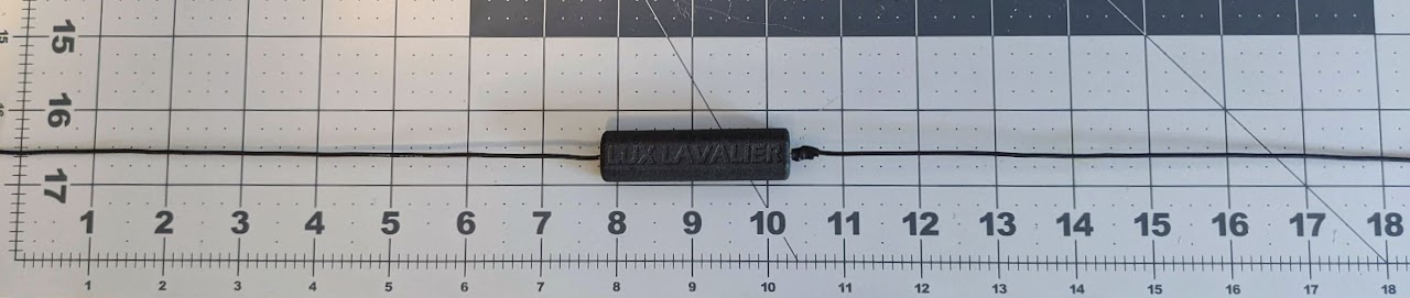
I’ll be trimming this one to 18” total length, so I laid it out with 9” in the center of the battery holder. Straighten and lay out the wires. Leave a little extra on both ends of the wires, as you can always trim it shorter. Measure twice, cut once. Cut the ends of the wires.
-
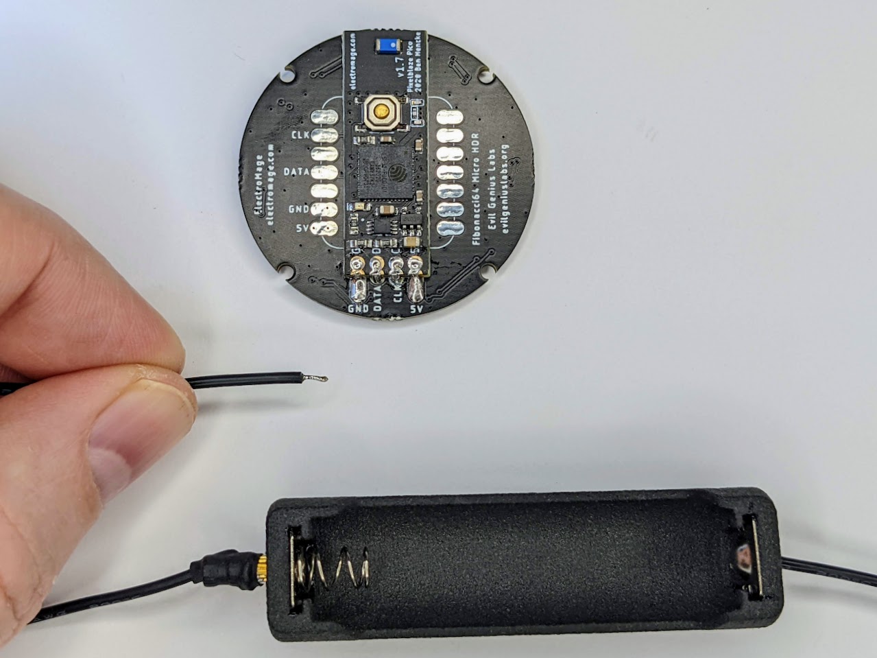
Strip about 1/8” (3mm) of insulation off both ends of the wires. The insulation is relatively soft silicone, and can usually be stripped off by pinching it between your fingernails. If you use wire cutters or strippers, be careful not to cut any of the metal wire strands inside.
-
Using a soldering iron and solder, tin the ends of both wires, melting and completely saturating and covering the ends.
-
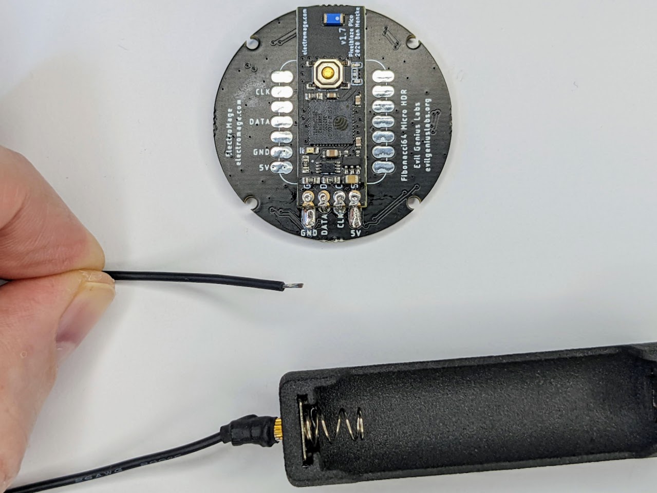
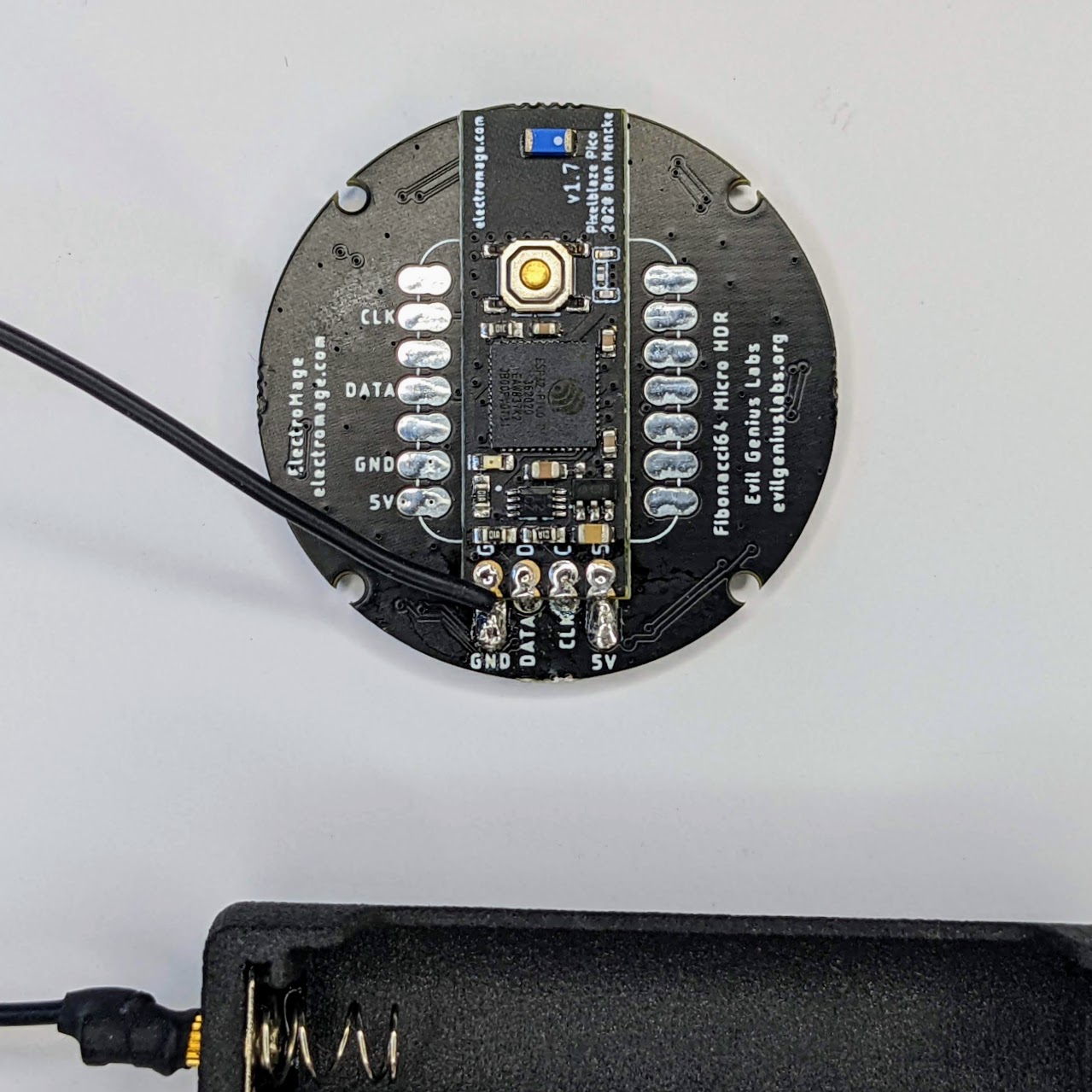
Place the wire on the GND pad, with the end of the wire pointing down, towards the edge of the round PCB. Hold the wire in place. Tweezers can help to prevent burning your fingers.
Gently press the soldering iron down onto the wire, reheating the solder, until it melts and joins with the solder blob on the GND pad on the PCB. Hold it in place, remove the soldering iron, and wait until the solder cools and hardens before releasing.
Repeat as necessary until the wire and pad are completely covered with a nice compact solder joint.
Ensure the GND and DATA pads are not bridged or connected with solder.
-
Repeat for the other end of the wire and the 5V pad.
-
Before proceeding, once again check to make sure there are no bridged solder joints between any of the pads. If you have a multimeter, you can use it to make sure there is no conductivity (or infinite resistance) between the pads.
-
Before assembling the case, insert a 14500 3.7V rechargeable lithium battery (not alkaline AA!) with the negative end against the spring in the battery holder. The light on the Pixelblaze Pico on the back should blink, and then the LEDs on the front should light up.
Remove the battery before proceeding to assemble the case.